Saturday, July 30, 2011

GPS datalogger with Arduino and SD card

I recently finished making a GPS datalogger with an Arduino, a micro-SD card, and an old USB GPS unit. It continuously logs the position from a GPS unit to an SD card.

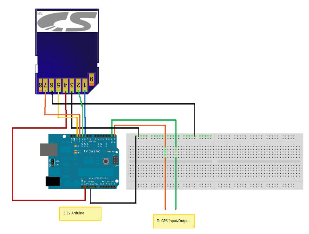
The connections are trivial with a 3.3V Arduino, since the micro-SD card has an SPI interface which the ATmega328 supports natively. I used a SiRF GPS unit, which outputs NMEA sentences at 4800bps. This was connected directly to the serial pins on the Arduino. With a 2GB SD card, we can log everything that the GPS outputs for well over a year, so I didn't bother filtering the GPS output.

The bill of materials is:
  1. 3.3V Arduino, or appropriate level shifters for the SD card
  2. GPS unit with a serial interface
  3. SD card or micro-SD card slot and memory card
  4. Some power source: car 12V plug, or USB, 9V battery
You can download the entire GPS datalogger Fritzing project. The connections and the schematic are shown below:


The associated Arduino program is trivial:
#include "FileLogger.h"

#define HEADER "Starting GPS logging.\r\n"
unsigned long header_length = sizeof(HEADER)-1;
byte header[] = HEADER;
unsigned long data_length;
byte gpsdata[128];

void setup(void) {
  Serial.begin(4800);
  FileLogger::append("data.log", header, header_length);
  data_length = 0;
}

void loop(void) {
  if (Serial.available() > 0) {
    gpsdata[data_length] = Serial.read();
    ++data_length;
    if(data_length > 127) { 
      FileLogger::append("data.log", gpsdata, data_length);
      data_length = 0;
    }
  }
}

The Seeduino Stalker is an excellent Arduino-SD card combination that can be used for this project.

This GPS datalogger can be powered from a 12V car plug for continuous logging of a car's position. This is useful to monitor the driving habits of your teenage child, or to log the route of a long cross-country drive. Another use is for logging bicycle trips automatically (powered from solar energy and a 9V battery for backup).

This device requires no user interaction. It starts logging when the device is powered on. If the Arduino has an LED connected to pin 13, it will blink when new data is being written to the card. At the end of a month, you can copy the contents of the SD card to a computer for analysis.

Most of the Arduino pins are unused, so there is hacking potential.

Sunday, July 17, 2011

Microcontroller driven LCD panel with voltage measurement, time, EEPROM for computers

I just finished making a circuit to drive a four line LCD panel from an Arduino. The project started out as a way to drive the LCD to display arbitrary information, but then evolved into a way to tell the time, read and write the EEPROM from the Atmel 328p, and measure voltage. I'm using many existing libraries: the Time library, and the two Controller LCD library.

The final functionality is:
  1. Commands are sent over USB using vi-line syntax. All commands start with ':' character.
  2. Segments the 40x4 display into 8 segments of 20 chars each. Segment 0 is column 0, line 0. Segment 1 is column 20 line 0. This allows an easy way to display up to eight different status updates. To write "hello world" in segment 3, you write ":s3helloworld\n" to the serial port.
  3. Read and write from EEPROM. The 1028 bytes of EEPROM is chunked into 8 segments of 128 bytes each. Segment 0 cannot be written to, which allows for 128 bytes of ROM. To write a segment 3, you index (:i3), then write (:wMySecretMessage\n). To read from EEPROM, you index first (:i3), then read the full segment (:r).
  4. Time can be read from the device (:t) and the time can be set using Unix time (:T1310349445).
  5. Voltage monitoring at analog pins can be toggled (:a). Voltages are displayed on the LCD (display shows all six pins in decivolts: 5.0v is written 50) and written in raw form on serial (relative to 1023. 1023 = 5V, 0=0V)

The entire Arduino source code is available as FourLinePanel.pde. It still has some debugging information left in, it prints the value of every new command it receives. This debugging could be removed. It supports a few commands:
:t Displays the time
:T<unix time> sets the time
:l<message>\n Writes message to current position
:sN<message>\n Writes message starting at segment N
:a Turns on analog voltage monitoring on LCD and serial
:r Reads 128 bytes from EEPROM at current location
:iN Index into segment N of the EEPROM
:w<data>\n Write data into EEPROM starting at current location

This requires one Atmega microcontroller, an LCD panel, two 22pF ceramic capacitors, and one 16Mhz crystal. To interface it with USB, a USB to serial cable might be required. In my design, I'm driving the entire project using power from the USB port. This minimises the need for voltage regulation and additional components: power over USB is usually clean. You can download the schematic for the FourLinePanel here.

To interface with a computer, you read and write to the serial port with 38400 bits per second, no flow control, and no parity bits. An example program to interface this with Python is given below.
import serial, time
# Set the time on the FourLinePanel for GMT+5hrs
# offset from GMT: Add 5hrs
offset = 5*3600
port = "/dev/ttyUSB0"
fourLine = serial.Serial(port, 38400);
fourLine.write(":T" + 
               str((int)(time.time() + offset))) 

There are five spare digital pins that could be used to drive a Real Time Clock or LEDs. These are marked as "Spare Digital (unused)" in the circuit diagram [png], and circuit diagram [ps]. The analog voltage testers can be used as handy ways to measure voltage at the desk when a multimeter isn't handy, or to constantly monitor the voltage drop across a device (like a photovoltaic cell).

Sunday, July 10, 2011

Dual HD 44780 Controller Liquid Crystal Library for Arduino

I came across a four row LCD panel while browsing at an electronics store: the model name was WM-C4004A. I wasn't sure if I could drive it through an Arduino but decided to try. It was easy to drive once I hunted down the datasheet for the WM C4004A, a dual HD44780 controller, and understood the controller.

There is a good Arduino library for driving HD 44780 compatible controllers and I modified the LiquidCrystal library to drive two separate controllers. The usage is identical to the LiquidCrystal library. You specify the Register Select (RS) and enable bits for both controllers, the data pins, and the rows and column per controller. Then you can seek() and write() through Arduino.

My modifications are available as the  LiquidCrystalDual library. Download the library: LiquidCrystalDual.tar.gz or LiquidCrystalDual.zip. Unzip and place the contents in the libraries/ directory in the arduino installation.

Here is a small example program (there is a detailed program in the examples/ menu in the Arduino IDE).

#include <LiquidCrystalDual.h>

// 2 controllers: RS, RW, EN1, EN2, D4, D5, D6, D7
// We have the RS (RS=12) line, *no* RW line (RW=-1),
// two enable lines (EN1=6, EN2=7),
// four data lines (D4=11, D5=10, D6=9, D7=8)
LiquidCrystalDual lcd(12, -1, 6, 7, 11, 10, 9, 8);

void setup()
{
  // I have 40 characters and two lines per controller.
  lcd.begin(40,2);

  // Move to the first column of second row.
  lcd.setCursor(0,0);
  lcd.print("Line 1: Hello");
  lcd.setCursor(0, 1);
  lcd.print("Line 2: World");
  // Move to the second controller
  lcd.setCursor(0, 2);
  lcd.print("Line 3: Four...");
  lcd.setCursor(0, 3);
  lcd.print("Line 4! Lines!");
}

void loop()
{
  // Do nothing.
}

Tuesday, July 05, 2011

Fun with Assembly Language

This is a quick page about my adventures with Linux assembly language, with links to resources, and some source code.

Why?

I won't fool you into thinking that assembly language is a useful tool: it isn't. By and large, if you want to get stuff done, you're much better off learning Python, C or Java. Assembly language is great if you're a tinkerer, and want to know what is going on inside your computer. Many people have written interesting tiny programs using assembly, which might be handy on embedded environments. Finally, there are some features that you can only get through assembly: low-level architecture features, getting around compiler limitations and understanding languages themselves. For me, assembly is just for fun!

Resources

I do all my programming on Linux, and it is one of the best environments to learn assembly. The tools are quite good, and there is some lovely documentation. If you don't already have Linux, get a copy of Knoppix, which is a live CD that lets you try out Linux without modifying your computer setup. Here is a list of books that I highly recommend.
  1. [PGU] - Programming From the Ground Up, by Jonathan Bartlett: an excellent introduction to x86 assembly language on Linux. The entire book is free for download. This one book is all you need, initially.
  2. [PAL] - Professional Assembly Language: another excellent introduction.
  3. [IPM] - Intel Programming Manuals: complete, in-depth information on architecture and assembly language. You're probably interested in Vol 1, 2A, 2B, 3A and 3B. It is meant as a reference: not a cover-to-cover read.
  4. [APM] - AMD x86-64 Programming Manuals: complete, in-depth information from AMD. Get all the volumes.

Fun with Assembly

So you got yourself a copy of [PGU], and want a challenge?
  1. We try to rewrite the first program from [PGU] as 01_exitValue.s. The expected return value is 999, but you get something else.
    1. Can you guess what the return value is without running the program?
    2. Can you explain why the return value is not 999?
    3. Can you write the program so that this problem can be caught by the assembler?
    4. 01_exitValue_Solution.s.
  2. We try to rewrite the second program from [PGU], using our understanding from the earlier problem, as 02_maximumValue.s. The expected return value is 214, but you get something else.
    1. Can you guess what the return value is without running the program?
    2. Can you explain why the return value is not 214?
    3. Can you write the program so that this problem can be caught by the assembler?
    4. 02_maximumValue_Solution.s.
  3. Here's an example for why you might need assembly language. Your mission is breaking into a program to steal a secret key. Some experienced hackers have isolated where the secret key is being passed to a secret function.
    1. secretFunction(char *useless, char *secret_key) calls validate() immediately upon starting. You job is to print secret_key inside validate. As an example, the file 03_keyIsHere.o contains the secret function that has the second argument as a key. You are only allowed to write a validate() method in a separate .s or .c file. Try not to modify the original object file. You are assured that the key is exactly 13 characters long. Try writing an assembly solution, and compile and run with gcc 03_keyIsHere_Solution.s 03_keyIsHere.o -o 03_keyIsHere; ./03_keyIsHere
    2. If the validate was called in the end, how does it change your solution?
    3. Can you use this trick to guess the local variables of secretFunction?
    4. In case the object file doesn't work for you, 03_keyIsHere.c contains the C source. The solution must not modify it.
    5. 03_keyIsHere_Solution.s Compile and run with gcc 03_keyIsHere_Solution.s 03_keyIsHere.c -o 03_keyIsHere; ./03_keyIsHere
  4. This is a more sophisticated example compared to the previous one. Having moved on in your career, you are faced with a new program that calls printf, and you have to inject code without a recompilation. The program 04_crackMe executes happily on its own. You know that printf is being called in it, and that on the first invocation, the calling function has a secret-key as its second parameter.
    1. secretFunction(char *useless, char *secret_key) calls printf() immediately upon starting. You job is to print secret_key. Most probably, you'll want to inject code into printf. The solution does not require modifying the original binary. You are assured that the key is exactly 13 characters long.
    2. Can you do this while continuing to print the original messages?
    3. In case the object file doesn't work for you, 04_crackMe.c contains the C source. Compile and run with gcc 04_crackMe.c -o 04_crackMe; ./04_crackMe . Remember that the solution does not require modifying the 04_crackMe binary or the C source code.
    4. 04_crackMe_Solution.s. Instructions on how to run it are inside the solution.
    5. Sufficiently pleased? Good, now carry it over to the next level by visiting this awesome page on making 13 equal to 17.

Cost effective (cheap!) USB Serial cable for any project

If you've been playing with microcontrollers, or hacking any sort of hardware, you know that it is great to be able to communicate with a computer. A usb cable is often the best option, since usb serial drivers are ubiquitous and easy to work with. However, cheap usb cables are difficult to come by. On this page, you will find instructions to build a very low cost USB serial cable, which can also supply +5V to a board. This is ideal for breadboard arduinos, but will also work great for any microcontroller or TTL circuit.

All instructions here are provided solely as a guide. If you miswire the cable, you might end up burning your computer, your electronic gadgets, or your house. I do not take personal responsibility for your actions.

Cost, parts, and capability

You need a Nokia CA-42 cable, a soldering iron and some method of determining continuity. A multimeter would be handy, but is not required. Assuming you have the tools, the CA-42 cable sells for $3 including free shipping from many sellers on eBay and Amazon. Since the cost of the cable is so low, online fraud is unlikely. The total cost of the project is $3, and you don't need any extra parts.
The final cable works on Linux, without requiring any extra drivers. Most cheap CA-42 cables are made using a PL-2303 chip, which is a cheap RS232 convertor. For data transmission, you only get two lines: RX and TX, but this is usually sufficient. You get +3V and +5V, which are very well regulated and clean sources of power. These could be directly attached to microcontroller boards. I have seen drivers for PL-2303 on Windows and Mac, and you should search for these over the Internet. You might need to mask the device ID, since the cable might announce itself as a Nokia phone cable. You don't need any drivers if you only want to use the cable as a power source.

Make it

The construction is trivial. This is what the cable looks like (image courtesy Timothy Small):

The pinout, from left to right is:
  1. This is body of the cable, and is not connected
  2. The missing pin, no connection
  3. No connection
  4. +3.3V, might be as low as +3V
  5. No connection
  6. RX
  7. TX
  8. GND
It might help to view the pin out diagram (hosted at nas-central.org).

To create the cable, cut the head near the top of the cable, as shown. When you cut the cable, try to match the color of the wire with the pinout given above. I've found the following colors, though you should check your own cable:
  • Black: Ground
  • Red: 3V
  • White: RX data
  • Blue: TX data
  • Green: no connection
Now, the cable has five wires: two are used for data (TX, RX), two are for power (+3.3, GND). There is an extra wire in there, which is useless for our purposes. So we repurpose this wire to carry the +5V connection from the USB port. In my cables, this wire has always been green, though you should check which wire, if any, is unused in your cable. The head of the cable comes off quite easily if you hold it and twist the metal USB connector as though it were a key. Connect the far right metal lead from the USB connector to the green wire. The green wire should be disconnected from the body, but the +5V connect should not be disconnected from the body: the PL-2303 requires +5V power to work.

Here is the final soldered assembly. In this image, the usb connector is the correct side up. For your reference, here is pin-out for the USB A connector. The soldering is done to the +5V wire.


Uses

The +5V and ground can be used to power an arduino or most Atmel Atmega AVR microprocessors. The TX wire (colored blue in my cable) goes into the TXD pin of microcontrollers (Arduino: digital 1), and the RX wire (colored white in my cable) goes into the RXD pin of microcontrollers (Arduino: digital 0). I've tested the power using an oscilloscope: the power in my cables is very clean. This means that you can avoid using a 7805 and other circuitry that would provide a clean +5V signal.


Credit: The idea for this cable is due to the the ARM9 Linkstation hackers.

Programming the NXT to communicate with Linux

This is Part 3 of a three-part series on programming the Lego NXT through Linux.
  1. Part 1 to setup the NXT-bluetooth connection
  2. Part 2 to setup your programming environment
If you have followed along, you are now ready to program in NXC.
Let's write a simple C program for Linux, and an NXC program for the NXT that communicate through Bluetooth. The interface of this program is totally dopey and unprofessional, but it demonstrates how to send information to the NXT and get information from it. The ideas are borrowed by notes from the CPSC 3720 Software Engineering course at the University of Lethbridge, in particular this handout. Here are the steps you need to follow.
  • Install Bluetooth libraries and GTK libraries on Linux. On Ubuntu, the command is:
    $ sudo apt-get install libbluetooth-dev \
           libgtk2.0-dev libc6-dev make gcc
    
  • Make the Tribot from the Mindstorms quickstart. This is the first project, the quick start.
  • Ensure that B is connected to the right motor, and C to the left motor. Leave A unconnected.
  • Now download my nxtBluetooth.tar.gz package to demonstrate Linux Bluetooth communication. Unpack it, and go through the files.
  • There are two programs: nx_soldier, which is the NX's program. It listens on Bluetooth and obeys the commands of the commander. The pc_commander is a GTK application that allows you to specify commands that the soldier will faithfully carry out.
  • There is a single place you have to edit to specify your NXT's address. Remember the times you changed 11:22:33:44:55:66 address above? Well, you need to open the pc_commander.c file and change this address to that of your NXT again.
  • Attach your NXT using the USB cable. Compile the programs with
    $ grep ADDRESS pc_commander.c       
    $ # Make sure you have the right address
    $ make nx_soldier.rxe
    $ make pc_commander && ./pc_commander
    
  • Run the nx_soldier program on the NXT.
  • Run the pc_commander on the Linux machine. Press the buttons to make the soldier move according to your wishes.
  • When you ask the soldier for his status, he always replies he is fine.
  • This program makes a good starting point: the code is reasonably well documented, and easy to adapt. You could try putting the bumper sensor on the TriBot, and modifying the nx_soldier so that he replies with "I am stuck" when it has hit a wall.

Setting up the Lego programming environment in Linux

This is Part 2 of programming the Lego NXT using Linux. Part 1 covers the Lego-Linux bluetooth connection.

If you're like me, you've used the graphical NXT programming environment for about twenty minutes before wrist pain and frustration sets in. I did not enjoy the graphical programming at all, and the fact that it did not work on Linux was another factor. Well, there is a very nice alternative, which is John Hansen's NXC language. It is a C-like language which you can program the NXT in. You'll hear a lot of references to BrixCC, which is an IDE for NBC and NXC. It doesn't exist for Linux, but any text editor works quite well. All features are supported, and you can write code that is more compact and faster than the graphical tool. Also, you can use NXC to allow your robot to communicate with your Linux computer over bluetooth! This is what you need to do to start using NXC.
  • Visit the excellent NXC beta release page . There is no stable release as of March 2009, but the beta is pretty rock solid. Forget the source code, it is made in Delphi and there is little documentation on how to compile it under Linux. Get the binary distribution. It consists of some very spare documentation and the nbc executable. Despite its name, it is also the NXC compiler. This will only work on x86 Linux.
  • Run nbc -help to learn the options. Really, this program needs a man page!
  • Visit the NXC documentation page and get the lovely NXC_Guide.pdf, a guide on how to program using NXC. Download it but don't look at it yet. It is a reference, not an introduction.
  • The real document you're looking for is Danny Benedettelli's NXC tutorial, which is far more useful than the guide. Download it, print it out, read it through and through.
  • To set up the USB communication, download setupNxtUSB.sh: shell script to perform USB settings for Linux communication with NXT.
  • Run it by itself as follows 
    $ chmod +x ./setupNxtUSB.sh;
    $ ./setupNxtUSB.sh
    
    This will prompt you for the root password when required. The file follows instructions from the page about Linux USB setup with NXT, so all credit to them. Feel free to edit the file if you suspect something went wrong. The script will prompt you with any errors that it encountered.
  • In case you aren't certain if the setup worked, plug in your NXT. You should see the word "USB" in the top left of the NXT display, and the output of the command ls -l /dev/lego* should show at least one device. My output is given as a reference
    $ ls -l /dev/lego*
    lrwxrwxrwx 1 root root 15 2009-04-19 17:45 /dev/legonxt-2-1 -> bus/usb/002/042
    
  • Write a sample program using Danny's guide.
  • Compile your program with nbc your_program.nxc -d -S=usb, where your_program.nxc is the name of your program.
  • Now the program has been compiled and loaded on to the NXT. It should appear in the "My Files" -> "Software Files" area of the NXT, from where you can run it!
  • There, that wasn't so hard! As you learn NXC, you'll realize that it is feature complete, and is a much more elegant way of programming the NXT.

Setting up NXT-Bluetooth support on Linux

So you want your NXT device to talk back to your Linux machine? Perhaps you want to control your robot through your computer. As a first step, you have to set up the Linux - NXT bluetooth connection. My setup is explained below.
  • Ubuntu Gutsy (7.10) Linux, though these instructions are not version dependant. The only instructions that depend on the distribution are the ones related to package installation (apt-get). If you know your distribution's package manager, you should have no trouble.
  • An x86 computer. Typically, you'll want a laptop with bluetooth support, so you can walk around with your NXT construction. A desktop will do just fine too. You need an x86 because the nbc binary only works on an x86.
  • A Lego Mindstorm NXT.
  • Bluetooth hardware on your linux machine.
  • The Linux packages: bluez-utils, python-bluez, bluez-hcidump, bluez-gnome, bluetooth
Make sure you have all the packages installed. On Ubuntu, you can run this command.

sudo apt-get install bluez-utils \
     python-bluez bluez-hcidump bluez-gnome bluetooth

Now, once all the packages are installed, make sure that your bluetooth hardware is supported and is running fine. One way to do this is to check for the bluetooth icon in the taskbar of Gnome.


You should be able to click on that icon and get a list of preferences. In case you are not sure if you device is getting recognized and used, check for lines similar to the ones below in the output of dmesg
 
[243203.060226] Bluetooth: HCI USB driver ver 2.9
[243203.063512] usbcore: registered new interface driver hci_usb

Now that you have a working bluetooth setup, you need to pair it with the NXT brick. First, you need to ensure that the serial service is started by selecting it in the preferences dialog from the bluetooth icon.


Now turn on your NXT Brick, and enter bluetooth settings, and turn bluetooth on. You can verify that bluetooth is turned on by looking in the top left of the NXT display. It should have a bluetooth icon. Now run the command sudo hcitool scan from a console. The output should contain a line for your NXT device. My device is called Snow, and I get the following output.

Scanning ...
 11:22:33:44:55:66 Snow

Great!. This is definite proof that your bluetooth device works, and that it can see your NXT. Time to set them up for pairing. Edit the file /etc/bluetooth/rfcomm.conf to contain the following block:

rfcomm0 {
        # Automatically bind the device at startup
        bind yes;

        # Bluetooth address of the device
        device 11:22:33:44:55:66;

        # RFCOMM channel for the connection
        channel 1;

        # Description of the connection
        comment "Snow Mindstorm";
}
Change the address 11:22:33:44:55:66 to match the output of your hcitool scan command that you made in the previous step.  Now run the command sudo /etc/init.d/bluetooth restart, and then rfcomm.  The output should contain your device's address.  A sample session is shown here:

$ sudo /etc/init.d/bluetooth restart
   * Restarting bluetooth            [ OK ]
$ rfcomm
rfcomm0: 11:22:33:44:55:66 channel 1 clean

Now, you need to pair your device. This is done with the following command
$ sudo l2ping 11:22:33:44:55:66
This will prompt the NXT to beep happily, asking for a passphrase.   The  number "1234" is already entered, so just accept it by pressing the  orange button.  Now your computer will want to know this passphrase.   Click on the button in the notification that pops up (example shown  below), and enter the same number as shown.  This is a one-time  procedure for each computer-NXT combination.


If you have a multi-seat (or multi-terminal) setup, this notification might be going to another seat, so check all notification areas on every terminal. If you don't know what multi-seat or multi-terminal setup is, ignore the previous statement. If all went well, your ping command should be able to send packets back and forth to the NXT. A happy sample output is shown below.

Ping: 11:22:33:44:55:66 from 00:09:DD:50:67:CE (data size 44) ...
4 bytes from 11:22:33:44:55:66 id 0 time 49.95ms
4 bytes from 11:22:33:44:55:66 id 1 time 85.71ms
4 bytes from 11:22:33:44:55:66 id 2 time 27.80ms
4 bytes from 11:22:33:44:55:66 id 3 time 54.80ms
4 bytes from 11:22:33:44:55:66 id 4 time 65.81ms
4 bytes from 11:22:33:44:55:66 id 5 time 47.80ms
4 bytes from 11:22:33:44:55:66 id 6 time 84.79ms
4 bytes from 11:22:33:44:55:66 id 7 time 45.81ms
 
Great!  So now your NXT is paired with the computer.  In order to communicate with the desktop, you need to download the NXT Python library.   Once you have downloaded and installed it, enter the sample program,  and you should be able to get the NXT's name and ID.  If you have any  problems at this stage, try rebooting the NXT brick, it sometimes helps.   After running the sample program, you should see your hostname in the  "My Contacts" in the NXT's bluetooth menu.  This verifies that you can  connect with the NXT, and have the NXT talk back to the desktop  computer.

(This is the stable home of the page that was earlier at vikram.eggwall.com)

Sunday, July 03, 2011

Hiking: Portola Redwoods State Park, July 4, 2010


This was our first time camping and hiking at the Portola Redwood State Park. The drive to Portola from San Jose is almost as long as the drive to Big Basin - about 1 hour. The park is nice, but we like Big Basin and Henry Cowell better.
There's a short trail starting behind the camp office, the Sequoia Nature trail I think, that takes you to a small stream with a bridge running across it. This is a great place to come by for a late evening walk from the campground.
The main hike marked in the map was on the Slate Creek trail. Took us a while to get to the trailhead, as you can see. We walked over 9 miles, spanning an elevation gain of 1000 - 1200 feet. A large map of the hike can be found here.

Friday, July 01, 2011

Hiking: Henry Coe State Park, Jun 26, 2010


The campgrounds at Henry Coe are very nice. There are just a few campgrounds, so it's a lot quieter, and the view is great. On a nearly-full-moon Friday night in late June, it was spectacular. The facilities are primitive, but well maintained.
We started hiking early, expecting most of the trails to be exposed to the sun, but our path was reasonably well shaded by trees and large shrubs. Okay - here's the 6.6 mile loop we did: started up the Monument Trail, made a left on Hobbs road, right on the Frog Lake Trail (there were many tiny, camouflaged frogs jumping all over!), right on the Middle Ridge trail, right on the Fish Trail, and then back to the Camp Headquarters via the Corral trail. The route was pretty well-marked all along.
Oh, and apart from being on the lookout for poison oak, also be on the lookout for ticks. Light colored clothing is probably a good idea - makes them easier to spot and de-tick.
A large map of the hike can be found here. The route covered roughly 1800 feet of elevation gain over a 6.6 mile stretch, but the uphill stretches are interspersed with easier stretches. Walking the same route in an anti-clockwise direction would probably be a lot more strenous.